Home >> YUANDA Valve
The purpose of pressure relief valves is to control or limit pressure fluctuations in the pipeline, to serve as protection for the system and to prevent the failure of instruments or equipment. They are commonly found in the water purification industry. A pressure relief valve is a safety device and in many cases the ultimate protection. It is important that the valve be maintained and operated at all times and under all circumstances.
Pressure relief valves are used in a range of applications where pressure levels are critical to uninterrupted and smooth mechanical performance. These include oil and gas, petrochemicals, and power generation using steam, air, gases or liquids. Pressure reducing valve operation is also used in multiple applications and chemical processing systems.
The operation of a pressure relief valve depends on the pilot valve sensing upstream pressure through its connection to the valve inlet. The valve and conductor remain closed until the inlet pressure exceeds the conductor setting. The valve opens quickly to relieve destructive overpressure and closes smoothly at an adjustable rate as the pressure returns below the set point.
- Low maintenance costs
- Flushing and testing operations are sanitary and minimal
- Eliminates surges and extends pipe life
- Effectively handles higher pressure applications
- Closes to prevent drips and leaks
- Quality materials reduce maintenance and provide the lowest long-term cost of ownership
- Adjustable shut-off speed
- Utilizes compressed air or plant air
The basic spring-loaded pressure relief valve was developed to meet the need for a simple, reliable, system actuator to provide overpressure protection.
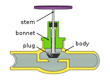
The valve consists of a valve inlet or nozzle mounted on a pressurized system, a disc that remains on the nozzle to prevent flow under normal system operating conditions, a spring that holds the disc closed, and a valve body/cover containing the operating element. The spring load can be adjusted to vary the pressure at which the valve opens.
As the relief valve begins to lift, the spring force increases. Therefore, the system pressure must increase if the lift force is to continue. For this reason, pressure relief valves allow an overpressure margin to reach full lift. For valves on unignited systems, this allowable overpressure is typically 10%. This margin is relatively small, and some means must be provided to help boost the force.
Therefore, most pressure relief valves have an auxiliary control or compression chamber to increase lift. As the disc begins to lift, fluid enters the control chamber, exposing a larger area of the disc to system pressure.
This causes an incremental change in force that overcompensates for the increase in spring force and causes the valve to open quickly. At the same time, the direction of fluid flow is reversed and the momentum effect from the change in flow direction further enhances the lift force. These effects combine to allow the valve to achieve maximum lift and maximum flow within the allowable overpressure limits. Because of the large valve flap area exposed to system pressure after the valve reaches lift, the valve will not close until the system pressure is reduced to a level below the set pressure. The design of the control chamber determines the location of the closing point.
The difference between the set pressure and the pressure at the closing point is called the relief pressure and is usually expressed as a percentage of the set pressure.
When the stack back pressure is variable, either a balanced bellows or balanced piston design is recommended. A typical balanced bellows is shown in the figure at right. The effective pressure area of the bellows or piston design is equal to the seat area of the valve flap. The bonnet is vented to ensure that the pressure area of the bellows or piston is always exposed to atmospheric pressure and to provide a signal when the bellows or piston begins to leak. Therefore, changes in back pressure have no effect on the set pressure. However, the back pressure may affect the flow rate.
A safety valve is a pressure relief valve actuated by inlet static pressure and characterized by a rapid opening or popping action. (It is typically used in steam and air service.)
Low Lift Safety Valves
A low lift safety valve is a type of safety valve in which the valve flap is automatically raised and the actual discharge area is determined by the position of the valve flap.
Full-opening Safety Valve
A full-opening safety valve is a type of safety valve in which the valve flap is automatically raised so that the actual discharge area does not depend on the position of the valve flap.
A pressure relief valve is a pressure relief device driven by inlet static pressure and has a gradual increase in lift, usually proportional to the increase in pressure over the opening pressure. It can be equipped with an enclosed spring-loaded housing and is suitable for closed discharge system applications, primarily for liquid service.
Safety relief valves
A safety relief valve is a pressure relief valve that features a rapid opening or popping action or, depending on the application, opens in proportion to the increase in pressure above the opening pressure, and can be used for liquid or compressible fluids.
Conventional Safety Relief Valves
A conventional safety relief valve is a pressure relief valve with a spring-loaded housing leading to the discharge side of the valve. Operating characteristics (opening pressure, closing pressure, and relief capacity) are directly affected by changes in the valve's back pressure.
Balanced Safety Relief Valves
A balanced safety relief valve is a type of pressure relief valve that incorporates a method of minimizing the effect of back pressure on operating characteristics (opening pressure, closing pressure, and relief capacity).
Pilot Operated Pressure Relief Valves
A pressure relief valve is a pressure relief valve in which the main pressure relief device is combined with and controlled by a self-acting auxiliary pressure relief valve.
Power-Actuated Pressure Relief Valves
A pressure relief valve is a pressure relief valve in which the primary pressure relief device is combined with and controlled by a device requiring external energy.
Temperature-Actuated Pressure Relief Valves
A temperature-driven pressure relief valve is a pressure relief valve that can be driven by external or internal temperature or pressure on the inlet side.
Vacuum Pressure Relief Valves
A vacuum relief valve is a pressure relief device designed to allow fluid to enter to prevent excessive internal vacuum. It is designed to re-close after normal conditions are restored and prevent further fluid flow.
While both terms refer to a valve used to relieve pressure from a pressurized system, they have somewhat different technical definitions. Typically, the term safety valve refers to a valve within a pressurized system that is used to control pressure for optimal system function. Pressure relief valves are designed to help your facility avoid system failure and to protect equipment from overpressure conditions.
On the other hand, the term safety valve refers to a pressure valve designed to protect people, property and processes. In other words, the term safety valve refers to a fail-safe, last-resort valve that will relieve pressure to prevent a disaster from occurring, usually when all other safety valves fail to adequately control the pressure within the system.
The general purpose of a safety valve and a pressure relief valve is the same. Both are pressure relief valves, and they are designed to relieve pressure in the event of any system overpressure. That said, safety valves and pressure relief valves have slightly different functions.
Safety valves are designed to control pressure in a system and are most commonly found in fluid or compressed air systems. These valves open as the system pressure increases. This means that they do not open fully when the system is slightly overpressurized. Instead, they open gradually, allowing the system to return to a preset pressure level. When that level is reached, the valve closes again.
One of the reasons for using safety valves - safety. Instead of controlling the pressure in the system, they are designed to release pressure immediately in the event of an emergency or system failure. Unlike safety valves, relief valves open fully immediately to avoid disaster, not to control system pressure.
Numerous codes and standards have been published around the world that address the design and application of pressure relief valves. One of the most widely used and recognized is the ASME Boiler and Pressure Vessel Code, commonly referred to as the ASME Code.
Most codes and standards are voluntary, which means they are available to manufacturers and users and can be written into procurement and construction specifications. the ASME Code is unique in the United States and Canada, having been adopted by most state and provincial legislatures and enforced by law.
The ASME Code provides rules for the design and construction of pressure vessels. Sections of the code cover combustion vessels, nuclear vessels, noncombustible vessels, and additional topics such as welding and nondestructive testing. Vessels built to the ASME Code must have overpressure protection. The type and design of overpressure protection devices allowed are detailed in the code.
Contact US
Related Information
ball valve working principletypes of ball valves in plumbingwhat is a globe valvemotorized gate valve suppliersCast Iron Non Return Valveglobe valve for steamplastic ball valve threadedforged gate valve manufacturershow to fix a leaking gate valvehow does a gate valve workball valve advantages and disadvantageshigh performance butterfly valve1/2 inch ball valve lowesButterfly Valve3/4 ball valve stainless steel4 Inch Check Valvebutterfly valve symbolstainless steel butterfly valveForged steel valvesCast Iron Silent Check Valve4 Check Valve Cast IronWafer butterfly valvelug style butterfly valvetriple offset butterfly valve1 inch brass ball valve priceball valve specificationwhat is the function of a globe valvegate valve factoryMarine Gate Valve ManufacturersNon Return Valve Suppliers Chinawhat is a gate valve4 butterfly valve6 Inch Cast Iron Check Valve4 ball valve stainless steel1.5 inch stainless steel ball valve5 inch pvc ball valve6 inch butterfly valveBall Valve Vs. Butterfly Valveflanged gate valve manufacturersball valves for salehow does bellows seal globe valve workpneumatic butterfly valvepvc butterfly valveCast Iron Dual Plate Check ValveCheck Valve With Handle