Home >> YUANDA Valve
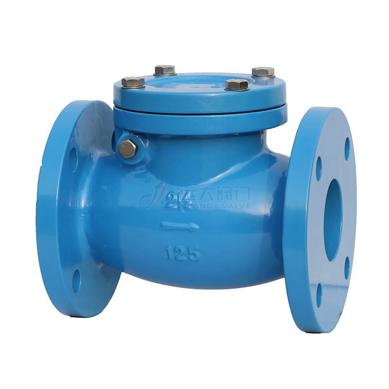
A check valve is a device that only allows the flow of fluids in one direction. They have two ports, one as an inlet for the media and one as the output for the media. Since they only allow media flow in one direction, they are commonly referred to as ‘one way valves’ or ‘non return valves.’ The main purpose of a check valve is to prevent backflow in the system. Figure 1 shows an example of a check valve.
A check valve relies on a pressure differential to work. They require a higher pressure on the input side of the valve than the output side to open the valve. When the pressure is higher on the outlet side (or the input side pressure is not high enough), the valve will close. Depending on the valve type, the closure mechanism is different. Unlike other valves, they do not need a handle, lever, actuator, or human to correctly work.
They are commonly installed in applications that backflow would cause an issue. However, since they are non return valves, they are a cheap, effective, and easy solution to solve a potential issue. Backflow can cause an issue if the backflow is contaminated, and therefore, contaminates the media upstream. For example, a sewer line will have a non return valve to ensure that waste can leave but not re-enter the system. They are also used if backflow will cause damage to equipment upstream that can only allow media to flow in one direction. For example, a reverse osmosis filter can only have water pass through it in one direction, so a one way valve is installed downstream to prevent this. There are various sizes, designs, and material to ensure there is a check valve for every application.
How does a check valve work?
Cracking Pressure
A check valve requires a minimum upstream pressure (pressure differential between inlet and outlet) to open the valve and allow flow through it. This minimum upstream pressure at which the valve opening occurs is called the check valve ‘cracking pressure’. The specific cracking pressure changes based on the valve design and size, so ensure that your system can generate this cracking pressure and that it is suitable for the application.
Closing
If the upstream pressure ever falls below the cracking pressure or there is a back pressure (flow attempting to move from the outlet to the inlet), then the valve will close. Depending on the check valve design, the closing mechanism can change. In short, the back pressure pushes a gate, ball, diaphragm, or disc against the orifice and seals it. Depending on the design the closing process can be assisted by a spring or gravity.
Installation Orientation
As a one way valve only works in one direction, it is crucial to know the correct installation orientation. Often times, there is an arrow on the valve housing to signal the flow direction. Otherwise, you will need to examine the valve to ensure it is installed in the intended flow direction. If it is backwards, flow will not be able to move through the system and a build-up of pressure could cause damage.
Spring Loaded In-Line
In-line spring loaded check valves are common, easy to understand, and have a simple design. Figure 1 shows an example of a spring loaded in-line check valve and Figure 2 shows the main components with arrows showing flow direction. When flow enters the input port of the valve, it has to have enough pressure (force) to overcome the cracking pressure and the spring force. Once overcome, it pushes the disc, opening the orifice and allowing flow to move through the valve. When the input pressure is no longer high enough, or there is a backpressure, then the backpressure and spring push the disc against the orifice and seal the valve shut. The spring, along with the short travel distance for the disc, allows for quick reaction time for closing. This valve design also prevents against pressure surges in the line, and therefore, also prevents a water hammer from occurring. Common types of spring loaded in-line check valves are also called ‘nozzle check valves’ or ‘silent check valves.’ They can be installed in a vertical or horizontal orientation. However, since they are in-line to the system, they have to be fully removed from the line to be inspected and/or perform maintenance.
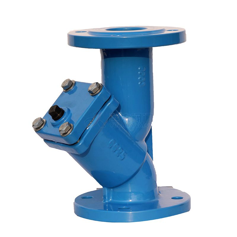
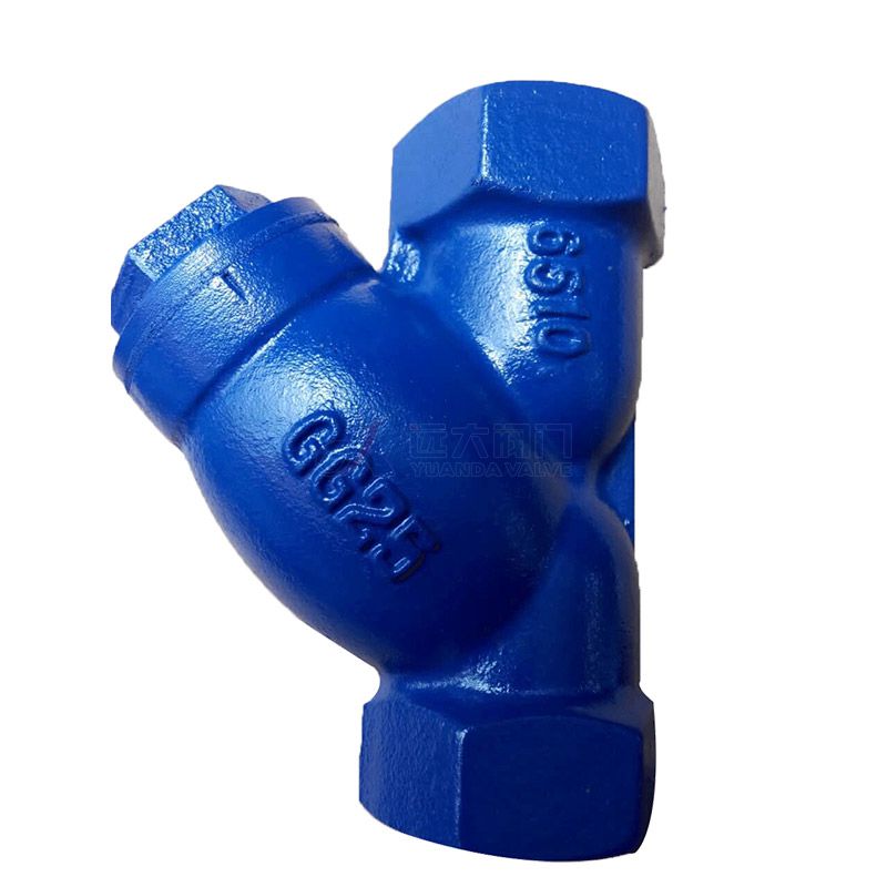
Spring Loaded Y
Spring loaded y-check valves operate very similar to in-line spring loaded check valves. The difference is that the spring and movable disc are positioned at an angle. This creates a ‘y’ shape, hence the name of the valve. It works the exact same as an in-line valve, but since the moveable components are at an angle it can be inspected and serviced while it is still connected to the system. However, they are larger and take up more room within the system.
Ball
A ball check valve uses a free-floating or spring-loaded ball that rests on the sealing seat to close the orifice. The sealing seat is normally conically tapered in order to guide the ball into the seat and create a positive seal, thereby, stopping reverse flow. When the pressure of the fluid in the inlet side exceeds the cracking pressure, the ball is dislodged from its seat and allows flow to occur. When the inlet pressure doesn’t exceed the cracking pressure, or there is back pressure, the ball will close with the back pressure or via the spring, effectively closing the orifice.
Diaphragm
Diaphragm check valves consist of a rubber diaphragm that flexes open when the inlet pressure is increased. Normally, these types of valves have a free-floating self-centering diaphragm, which makes them normally open (NO). These means that there is no “cracking pressure”, however, they can be normally closed (NC) and then it requires an inlet pressure to overcome the diaphragms elasticity. Figure 5 on the left shows a normally open diaphragm check valve as there is ‘minimal’ inlet pressure and the media still gets through. As inlet pressure increases, the diaphragm will flex open more allowing flow through, as seen in Figure 5 in the middle. If backpressure occurs (or it is a normally closed diaphragm check valve) the diaphragm will be forced against the opening and seal it to prevent any backflow, as seen in Figure 5 on the right. Due to the normally open nature, diaphragm check valves are ideal for low-pressure or vacuum applications.
Lift
A lift check valve consists of a guided disc that raises (lifts) up off of the valve seat to allow media flow. It requires a cracking pressure to overcome gravity and/or a spring and the guide keeps the disc in a vertical line, so that the disc can be re-seated with the correct alignment and seal. Most commonly, lift check valves require the media to make a 90-degree turn, as seen in Figure 6, but there are lift check valves that are in-line or at an angle. As the inlet pressure decreases below the cracking pressure or there is a backpressure, the valve will close by gravity, spring, and/or by using the backpressure. If there is no spring to assist in closing, mounting orientation in regard to gravity is important to ensure that the disc will swing shut with gravity.
Lift check valve
Swing
Swing check valves are also commonly referred to as ‘tilting-disc’ check valves. They consist of a disc that is on a hinge (or trunnion) that swings open with an inlet pressure. As inlet pressure decreases or there is a backflow, the disc will swing shut. If there is no spring to assist in closing, mounting orientation in regard to gravity is important to ensure that the disc will swing shut with gravity. Figure 7 shows an example of a swing check valve.
Swing check valve
Stop
A stop check valve is typically a spring loaded y-check valve or a lift check valve, but it has a manual override feature. This allows them to function as a normal check valve and prevent backflow, however, there is an external mechanism that can be used to override it and maintain the valve in an open or closed state. Therefore, this valve can function as two valves in one. They are commonly used in power plants, boiler circulation, steam generators, turbine cooling, safety systems.
Stop check valve
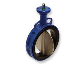
Butterfly or Wafer
Butterfly check valves and a wafer check valves can be used interchangeably. They consist of a butterfly, or wafer, style disc that is on a hinge and a spring. When inlet pressure overcomes the cracking pressure, the two sides open, as seen in Figure 9. When the inlet pressure decreases or there is a backflow, the spring on the hinge (or backpressure) will close the disc effectively sealing it. This valve types allows a straight media flow with minimal obstruction.
Duckbill Valve
Duckbill valves allow flow to proceed through a soft tube of which the end has a natural flattened shape, as seen in Figure 10. This flattened shape resembles a duck beak, hence the name of the check valve type. The flow opens the flattened end of the duckbill, permitting fluid to pass as seen in Figure 11 on the left. When pressure is removed from the inlet side, the duckbill end returns to its flattened state, thereby cutting off the flow as seen in Figure 11 on the right.
Foot Valve
A foot valve is simply a check valve type in combination with a strainer on the inlet side that is installed at the end of a section of piping/hosing as their input doesn’t have a connection point. Common check valve types included in a foot valve are in-line spring assisted or an in-line ball check valve, therefore, they only allow flow in one direction and are assisted in closing with a spring. They have a strainer on the inlet side to prevent debris from entering the check valve that could clog or damage something downstream. They are typically installed at the end of a pump suction line of a water well, fuel tank, or any other application where the suction line is situated below the pump. Therefore, they can be used to keep pumps primed, prevent liquid from siphoning back, and keeping debris out of the line. Figure 12 shows an example of a foot valve.
Brass
Brass check valves have excellent properties for applications that are using air, water, oil, or fuels. However, it is not resistant to seawater, purified water, or chlorinated water. They are less resistant to heat and corrosion compared to stainless steel and are typically used for smaller applications with low pressure.
Stainless Steel
Stainless check valves have superior corrosion resistance, heat resistance, low-temperature resistance and excellent mechanical properties. For applications that don’t require high durability or resistance, it stainless steel is typically not a cost-effective solution when compared to PVC or brass check valves.
PVC (Polyvinyl Chloride)
PVC check valves are frequently used in irrigation and water management systems. They are corrosion resistant to most corrosive media like seawater, acids, bases, chloride solutions, and organic solvents. However, they are not resistant to aromatic and chlorinated hydrocarbons and typically have a max temperature around 60°C.
Polypropylene (PP)
Polypropylene check valves are used for water, aggressive media, and liquid food products. They are resistant to most corrosive media like inorganic acids, bases, and aqueous solutions that rapidly corrode metals. However, they are not resistant to concentrated acids and oxidizing agents and typically have a max temperature around 80°C.
Selection Criteria
Check valves have the following criteria to consider when selecting one for your application:
Material compatibility with the medium
Line size for connection points
Max pressure and cracking pressure requirement
Installation orientation horizontal or vertical
Envelope dimensions
Accessibility needs for inspections and repairs
Temperature (external and media)
Applications
Due to how check valves function, they are typically used for one of four different reasons in a variety of applications:
To protect equipment downstream form backflow damage
To prevent contamination due to reverse flow
To prevent siphoning
To keep a vacuum seal
Due to their function, they are used in almost every industry. They are used on common household appliances, like dishwashers, washing machines, and waste water lines. For industrial purposes, they are used on boilers, furnaces, gas systems, pumping applications, or vacuum systems. They are also frequently used on water and CO2 lines as aquarium check valves. Two of the most common check valve applications are for water and air, so those are discussed in more depth below.
Check Valves for Water
Check valves are used in numerous water applications, like drinking water and waste water applications, and are simply called one way water valves. For drinking water applications, they ensure that no media from the environment (outlet side of the valve) can enter the system with the safe clean drinking water and contaminate it. For waste water applications, they ensure that the waste water cannot re-enter the system and cause an overflow or additional contamination. For water pumping applications, often times a foot valve is used to ensure no debris will enter the line and to keep internal pressure for priming purposes. Duckbill valves can also be used for discharges on water lines. Sump pump check valves ensure that the discharged water does not come back into the sump pump with gravity when the pump is turned off.
Pneumatic Check Valve
A pneumatic check valve, or air check valve, allows the flow of air in and prevents it from going out. They are often simply just called one way air valves. The most common application is for an air compressor. They allow the compressor to keep certain parts pressurized and other parts de-pressurized. They can be located on a piston compressor (inlet and outlet), air receiver, discharge pipe, etc.
What is the check valve symbol?
The check valve symbol can be seen in Figure 13. It points in the orientation that it allows the flow with a vertical line showing it doesn’t allow backflow.
What is the purpose of a check valve?
The main purpose of a check valve in a system is to prevent backflow, which could damage equipment or contaminate media upstream.
What are common check valve problems?
Common check valve problems are: noise, water hammer, vibration, reverse flow, sticking, leakage, and component wear/damage. To prevent issues, it is crucial that a check valve is specified correctly for the application and media. The two most common issues due to improper specification are reverse flow and water hammer. For both issues, a fast-closing check valve should be used. Reverse flow can occur if the check valve doesn’t close fast enough and water hammer can occur if pressure surges occur causing shock waves within the media.
Will a check valve stop water hammer?
A check valve can prevent a water hammer if it is fast acting. This prevents pressure surges, which creates shock waves throughout the media. These shock waves can damage equipment, pipe supports, and even rupture pipelines due to the vibration.
What orientation should a check valve be installed?
Check valves need to be installed in accordance to their inlet and outlet, which is often shown as an arrow on the valve housing. As they only allow flow in one direction, if they are installed backwards, they will not work properly. In terms of horizontal or vertical, it depends on your valve design type. If it has a spring, any orientation is okay. If no spring, gravity can affect check valve operation, so ensuring you know the inner components will ensure you install it correctly in a horizontal or vertical manner.
Why is my check valve not working?
When a check valve doesn’t work, it allows backflow. Three possible reasons for this are: sticking, leakage, or slow closing. If there isn’t a filter in the line, dirt or debris can be trapped between the disc and body keeping it open. Due to wear or corroding media on the material, the disc or seat can become damaged or torn preventing a proper seal and allowing backflow. If the valve closes too slow, minimal backflow can enter before a proper seal can occur. Ensure that gravity is helping the design, and/or your spring is quick enough to close the valve rapidly.
Contact US
Related Information
Marine Gate Valve Manufacturerswhat is the function of a globe valve1 inch brass ball valve pricehow to tell if a gate valve is open or closedGate Valvebrass ball valve temperature ratingCast Iron Non Return ValveChina Gate valveCast Check Valvehigh pressure gate valves manufacturer6 Inch Pvc Swing Check Valvehow to replace the packing on a gate valveexhaust butterfly valvehow to identify gate and globe valve4 inch ball valve price6 inch butterfly valveflanged gate valve manufacturersCheck Valve With Handletypes of ball valves in plumbing3/4 male threaded ball valveball valves for salewhat does the globe valve doBrass valvesCast Iron Wafer Check Valveglobe valve symbolswhere to place globe valve on an irrigation systemglobe valve diagramWhere globe valve is usedglobe valve for steamWhere are solenoid valves usedball valve life expectancywhat is a gate valve1/2 inch ball valve lowes4 Inch Check ValveCast Iron Dual Plate Check Valve3 Inch Check Valvehow to replace a gate valve3/4 ball valve stainless steelwhat is a globe valve used forglobe valve direction of flowball valve advantages and disadvantageslug style butterfly valve12 Inch Check ValveCast Iron Ball Check ValveButterfly Valve