Home >> YUANDA Valve
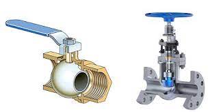
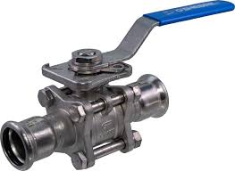
As ball valves become more popular, gate valves may not be used as often as they used to be, but for some applications, they are perfect for the job. Irrigation applications still use gate valves because some of the drawbacks that caused ball valves to replace them are not an issue for irrigation.
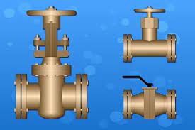
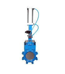
Gate and knife valves are linear motion valves that include a gate's flat closing element. 09SGS-15 opens by turning the handwheel counterclockwise and closes by turning clockwise, with the gate inside the valve sliding up and down. You simply push or pull the handle for knife valves to slide the gate. Both valves move the gate into the flow stream to completely stop fluid flow.
Gate and knife valves are designed to minimize the pressure drop across the valve. In the fully open position, the diameter of the opening through which the fluid passes is equal to the diameter of the pipe, and the direction of flow remains the same.
Gate valves can be found wherever economical shutoff is required. Gate valves are well suited for any application involving slurries, as the gate can pass right through. Gate valves are also common in applications where liquids such as heavy oils, light greases, varnishes, and other non-flammable liquids are used.
Gate valves are ideal for irrigation systems that require high flow rates. Gate valves are slow to close because it takes several turns to open or close the gate, so flow starts and stops more slowly than ball valves. Gate valves are extremely common in irrigation applications because the closing speed is not as important as the strength to support high flow rates.
Most gate valves have metal-to-metal seats that do not create a positive seal, sometimes resulting in leakage, while ball valves close tightly. Gate valves tend to clog if not used for some time, causing stem packing to leak.
Gate valves tend to be larger than ball valves. They stick out more, which is not ideal for tight spaces. For some applications, ball valves would be a better choice because they can provide a leak-free seal.
Gate valves can be used anywhere throttling capability is needed, but this is usually not recommended because the vibration of the valve flap can cause corrosion of the seat and flap, which can cause the valve to leak over time.
While gate valves may not be the most popular valves on the market, they are still a suitable choice for certain functions. Please note the location and situation in which you need the valve to determine which is best for you.
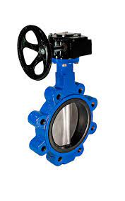
Gate valves control media flow by raising the gate (opening) and lowering it (closing). The distinguishing feature of a gate valve is the straight-through passage, which causes minimal pressure loss across the valve. Unlike butterfly valves, the gate valve's clear bore allows a pipe cleaner to pass through during pipe cleaning. Gate valves are available in various options, including various sizes, materials, temperature and pressure ratings, and gate and bonnet designs.
Gate valves tend to be slightly less expensive than ball valves of the same size and quality. They are slower to actuate than right angle rotary valves and are suitable for applications where valve operation is infrequent, such as isolation valves. Gate valves should be fully open or closed rather than regulating flow. Automatic gate valves exist with electric or pneumatic actuators, but manual gate valves are cost-effective because they are used infrequently.
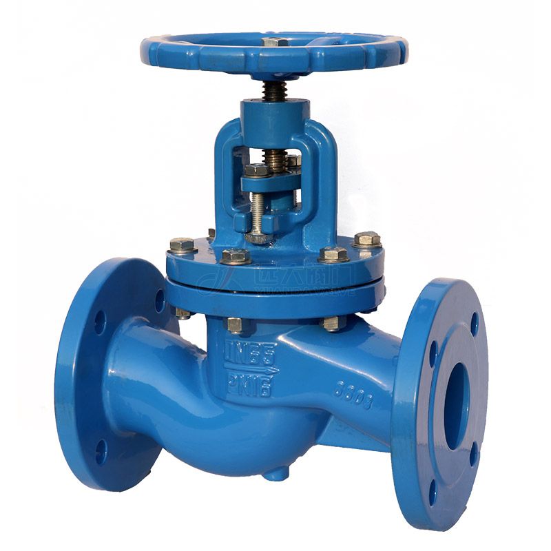
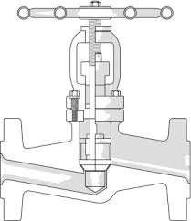
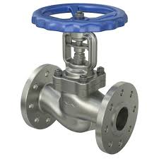
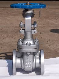
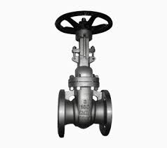
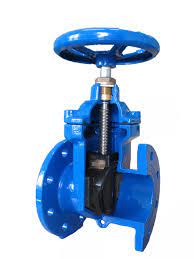
The main components of a gate valve are the handwheel, spindle, gasket, bonnet, body, flange, and gate. The main operating mechanism is straightforward. Turning the handwheel rotates the stem and moves the gate up or down through the threads. They require more than 360° of rotation to fully open/close the valve. Lift the gate from the flow path, and the valve opens. Lowering the gate to its closed position will seal the bore, causing the valve to close completely.
For gate valves, the relationship between gate vertical travel and flow is non-linear, with the greatest change occurring near closure. When used to regulate flow, the relatively high flow rate during partial opening can cause wear on the gate and seat, while the gate may vibrate, thus shortening the valve's life.
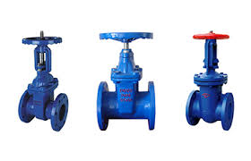
Gate valves are available in various designs, each using different technologies to meet the requirements of various applications.
The bonnet protects the internal components of the gate valve. It is screwed or bolted into the valve body to form a leak-proof seal. Therefore, it is removable for repair or maintenance purposes. The gate valve can have a screw-on, live-joint, bolted, or pressure-sealed bonnet depending on the application.
Screw-on bonnets are the simplest construction. They are common in small valves and provide a durable, leak-proof seal.
The union cap is held in place by a union nut. The union nut is located on the lower edge of the bonnet and screws into the valve body threads. This type of design ensures that the leak-proof seal created by the nut will not deteriorate with frequent cap removal. For this reason, live-joint bonnets are common in applications that require periodic inspection or maintenance.
Bolted bonnets provide a seal in larger valves and higher pressure applications. The bonnet and valve body are flanged and bolted together in this type.
Pressure-sealed gate valves are ideal for high-pressure applications (over 15 MPa). This type of construction uses internal pressure to create a better seal. Pressure-sealed bonnets have a downward-facing cup that is inserted into the valve body. As the internal fluid pressure increases, the cup is forced outward, resulting in an improved seal.
Gates are available in various designs and technologies to provide an effective seal for different applications.
In most gate valves, the gate is wedge-shaped and sits on two angled seats. In addition to the primary force generated by fluid pressure, the high wedging force on the seats created by the tightening of the stem helps to seal. The wedge-shaped gate does not stick to the seat at high fluid pressure differentials and has a longer service life because there is less "friction" on the seat.
Gate valves are also available in parallel form, where the gate is flat, and the seat is parallel. Parallel gate valves use line pressure and positioning to achieve a tight seal. Parallel gates consist of two parts with a spring in the middle. The spring pushes the parts against the seat to enhance the seal. Due to their inherent design, parallel gate valves offer safety advantages in high-temperature applications. In a wedge gate valve, the additional compression load on the seat may result in thermal bonding and restricted valve opening due to expansion. In addition, the absence of wedging action in parallel gates results in relatively low closing torque, leading to smaller, less expensive actuators or less manual operation. Because they slide into place, parallel gates keep dirt away from the seating surface.
A slab gate, also known as a straight-through conduit gate, is a one-piece gate that includes an orifice size hole. In the open position, the bore is aligned with two seat rings. This alignment produces a smooth flow with minimal turbulence. This unique design minimizes pressure loss in the system and is ideal for transporting crude oil and natural gas liquids (NGLs). The valve seat is kept clean. However, the disc cavity can trap foreign material. As a result, the cavity typically has a built-in plug to drain foreign material buildup for maintenance purposes.
Expansion gate valves have two slab gates matched together to provide a seal by the mechanical expansion of the gate. When lifted, both slab-pouring ports allow media flow. Through a step in the valve body, the upward force on one plate and the stop of the second plate allow outward mechanical expansion for proper sealing. When closed, the slab gate blocks the media flow, and the downward force on one slab (stem) and the upward force (step in the body) allow outward mechanical expansion for proper sealing.
These valves provide an effective seal for both the upstream and downstream seats. This seal makes them ideal for applications such as isolation valves in power plants, shutoff valves in process systems, and high-temperature valves in refineries.
Knife gate valves are suitable for viscous fluids and dry bulk solids. The gate has only one piece of metal, usually pointed. These valves are self-cleaning as they pass through the seat each time they open and close.
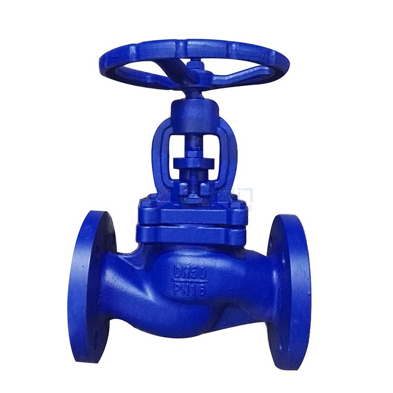
The door is raised and lowered by the rotation of a threaded stem. A manual wheel or actuator rotates the stem. Depending on the design, the stem is considered raised or non-raised. Therefore, as you rotate the stem, it raises or stays in place as it rotates.
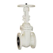
The male thread and yoke (OS&Y), also known as the rising stem, is secured to the door. Therefore, the threads are located on the drive side. Therefore, when the door is raised or lowered, the stem moves up and down with it. As a result, they have built-in visual indicators of valve status and are easy to lubricate. Because they have moving parts, they cannot be used with bevel gears or actuators. Therefore, rising gate valves are suitable for manual actuation.
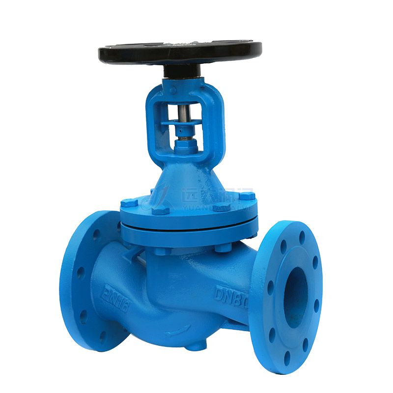
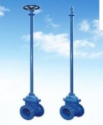
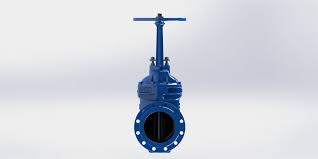
On the other hand, non-rising stems are fixed to the actuator and screwed into the gate. An indicator is usually screwed onto the stem to indicate the open or closed status of the valve. Non-rising gate valves are common in underground installations and applications where limited vertical space.
A gate valve controls the media flow by raising the gate (open) and lowering the gate (closed).
The threaded rod moves the gate up and down by turning the manual handle. As the gate rises, it opens, and as it lowers, it closes the media flow.
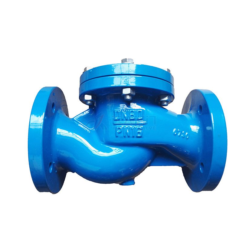
Gate valves are used to open and close the flow control.
Contact US
Related Information
what is the function of a globe valveglobe valve steamglobe valve flow directionKeystone Butterfly Valvewedge gate valve manufacturershow a gate valve worksglobe valve direction of flowwhat is ball valve in plumbingCast Steel Valvesgate valve factorypneumatic butterfly valveWhere gate valve is usedCast Flow Check ValveAngle globe valve8 Inch Check Valvemotorized gate valve suppliersplastic ball valve threadedhow to replace the packing on a gate valveBrass valveshow to fix a leaking gate valveglobe valve flow controlhow does bellows seal globe valve workangled globe valveNon Return Valve Suppliers Chinahow to repair gate valve3 way globe valvestainless steel butterfly valveCast iron valvewhere to place globe valve on an irrigation systemWhere would a double check valve be usedwhat does the globe valve dohigh pressure gate valves manufacturerwhat is a globe valve used forCast Iron Lift Check ValveChina Check Valve SupplierBall valve selection guideCheck Valve Price3/4 male threaded ball valvepvc butterfly valveball valve specification4 butterfly valveflanged gate valve manufacturers4 Check Valve Cast IronGate Valve Vs. Ball Valve6 butterfly valve